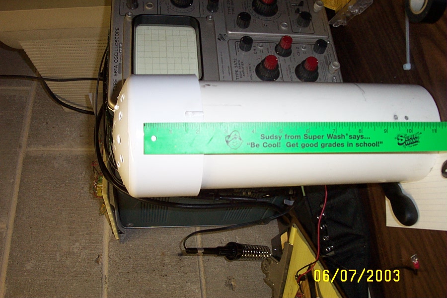
- Housing - For the housing I used a 1
foot section of 4 inch
PVC pipe, 1 4 inch cap on the bottom, and 1 6 inch cap for the top. This
limits the width of the circuit board to 4 inches, but this should be plenty.
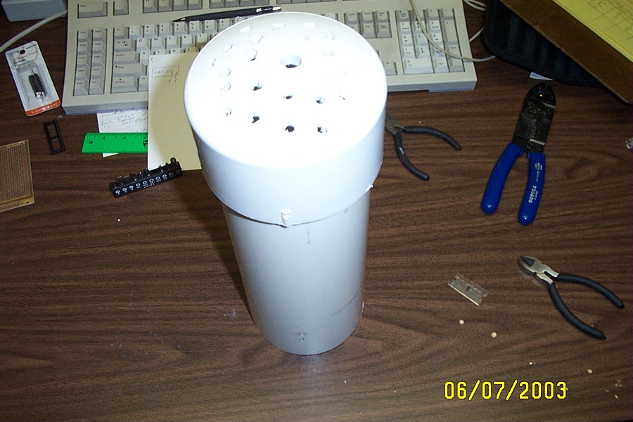
I drilled a few holes in the bottom cap to allow the wires to pass through,
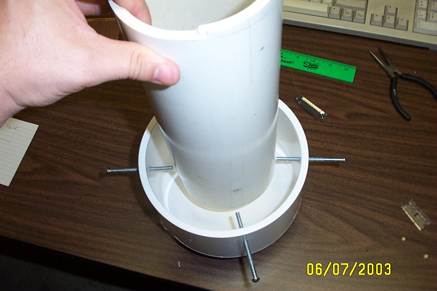
and also to allow for airflow. To secure the top cap I drilled 4 holes
through the 6 inch cap and 4 inch housing. I then used 4 screws to
secure the cap to the housing. This leaves an approximately 1 inch gap
between the top cap and housing so that any heat generated by the electronics
can flow up and out. The 6 inch cap keeps moisture out while letting air
flow through. I sealed the bottom cap with PVC cement to keep moisture from
collecting around the rim. This imposes the requirement that all electronics
access be done through the top of the housing. I am in Minnesota where water
freezes. If allowed to collect and freeze it would cause problems eventually.
If you are in a warmer climate then you may be able to get away with not
sealing the bottom cap.
- Electronics - Here is the schematic. I left the pin numbers off of the
sensors because some of them (HIH) do not have pin numbers. The leads and
what they correspond to are detailed in the data sheets for the sensor. See
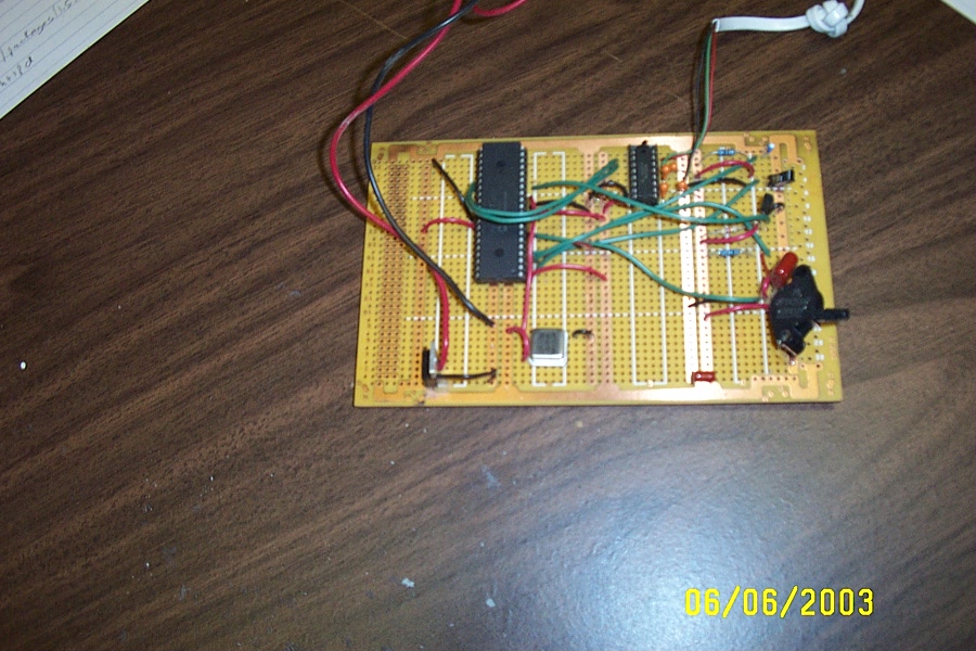
the data sheet for the particular sensor for more information. For the PCB I
used cheap perfboard. Perfboard
is easy to find, cheap and works well for prototyping. If you don't like
soldering, you could use a piece of solderless breadboard instead (what I
prototyped on). As far as
component placement goes, try to put the 7805 regulator toward the top of the
housing away from the sensors. It will generate some heat. Put the sensors
toward the bottom of the housing where fresh air will be drawn in. The PIC
micro-controller and the serial line driver can go anywhere. I used a 12V power
supply (what I had laying around) to hook up to the 7805 voltage regulator. I
soldered the power supply wires directly to the board and used spade
connectors for disconects. I used telephone cord to connect the
MAX232 to the PC. I didn't have any of the standoff
telephone plugs, so I used a modular block (what I had laying around) and
secured it to the perfboard. A standoff would be much better if you have one. On the PC end
of the phone cord I wanted to be able to plug in to DB25 or DB9 since I have
both. To do this I bought the connectors and wired
them to a crimped on phone
connector. I then used a female to female block so that the connector type
could be switched out. If you only need one or the other you can wire the
connector directly.